
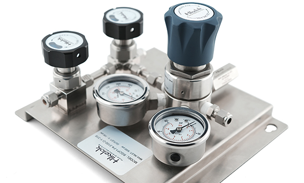
Pengoperasian sistem pipa fluida industri yang stabil bergantung pada aksesori pengatur tekanan berkualitas tinggi untuk perlindungan. Sebagai komponen pengatur tekanan inti, regulator penurun tekanan dapat secara akurat menurunkan tekanan tinggi media yang masuk ke tekanan rendah yang dibutuhkan untuk kondisi kerja, sehingga secara efektif memastikan pengoperasian sistem secara keseluruhan yang aman.
ItuSeri Hikelok PR1Regulator pengurang tekanan presisi ini mencakup secara komprehensif sirkuit gas laboratorium, pasokan gas kalibrasi analyzer, pengaturan tekanan silinder gas industri khusus, pengiriman bahan bakar kromatografi, dan skenario lainnya. Dengan teknologi kontrol tekanan yang presisi, regulator ini memberikan jaminan pengaturan tekanan profesional yang aman dan stabil untuk industri dan penelitian ilmiah.
01 Fitur Produk
*desain ringkas
*Penyesuaian sensitivitas tinggi
*Dirancang untuk meminimalkan polusi dan mengatur secara tepat gas korosif, non-korosif, atau beracun.
*Penyegelan diafragma logam ke logam pada badan regulator memastikan kebocoran eksternal minimal.
*Diafragma bergelombang memberikan presisi yang sangat baik dan masa pakai yang lama.
*Pemasangan panel tersedia
02 Parameter Produk
Parameter
Indikator Teknis
Tekanan Masuk Maksimum
3500 psig (≈ 241 bar)
Berbagai Rentang Tekanan Keluaran Opsional
0-25 psig (0-1,7 bar), 0-50 psig (0-3,4 bar), 0-100 psig (0-6,9 bar), 0-250 psig (0-17,2 bar), 0-500 psig (0-34,5 bar)
Tekanan Uji Desain
150% dari tekanan kerja maksimum dengan margin keamanan yang memadai.
Kinerja Kebocoran
Kebocoran gelembung internal nol; laju kebocoran helium eksternal ≤ 2×10⁻⁸ atm・cc/detik, cocok untuk lingkungan media dengan kemurnian tinggi dan beracun.
Kemampuan Adaptasi Suhu yang Luas
Tiga pilihan material dudukan regulator untuk rentang suhu yang berbeda: • PCTFE: -40℃ ~ 80℃
• PEEK: -40℃ ~ 200℃
• PI: -40℃ ~ 260℃
Koefisien Aliran (Cv)
0,06
03 Struktur Inti
Komponen penyesuaian:pegangan, pegas jangkauan (atur tekanan keluaran)
Komponen penginderaan:diafragma (elemen penginderaan tekanan inti, yang memisahkan ruang atas dan bawah)
Komponen eksekusi:batang, kumparan, dudukan (mengontrol aliran fluida hidup/mati dan pengaturan aliran)
Tubuh:termasuk saluran masuk, saluran keluar, dan saluran umpan balik (mengarahkan tekanan keluar ke ruang bawah diafragma)
04 Prinsip kerja
1. Pengaturan tekanan (kesetimbangan awal)
Putar gagangnya, tekan pegas pengatur jarak, dan hasilkan gaya dorong ke bawah.
Gaya pegas mendorong diafragma, batang, dan kumparan ke bawah, membuka lubang regulator.
Medium bertekanan tinggi mengalir masuk dari saluran masuk, mengalami penyempitan dan pengurangan tekanan, lalu mengalir menuju saluran keluar.
Tekanan keluaran bekerja pada bagian bawah diafragma, menghasilkan gaya umpan balik ke atas.
Ketika gaya pegas (ke bawah) sama dengan gaya umpan balik tekanan keluaran (ke atas), kumparan tetap diam dan tekanan keluaran stabil pada nilai yang telah ditetapkan.
2. Proses penyesuaian dinamis
Skenario A:Penurunan tekanan keluaran (peningkatan penggunaan hilir)
Gaya umpan balik pada sisi bawah diafragma berkurang → gaya pegas > gaya umpan balik.
Diafragma menggerakkan kumparan ke bawah → bukaan regulator meningkat → laju aliran media meningkat → tekanan keluaran naik ke nilai yang ditetapkan.
Skenario B:Peningkatan tekanan keluaran (penurunan penggunaan hilir)
Gaya umpan balik pada sisi bawah diafragma meningkat → gaya umpan balik > gaya pegas.
Diafragma menggerakkan kumparan ke atas → bukaan regulator mengecil → laju aliran medium menurun → tekanan keluaran turun ke nilai yang ditetapkan.
05 Kurva karakteristik aliran
Di bawah tekanan tinggi, kurva kinerja stabilisasi regulator penurun tekanan adalah:
Pada tekanan sedang dan rendah, kurva kinerja stabilisasi regulator pengurang tekanan adalah:
Analisis kurva: Sumbu horizontal mewakili laju aliran nitrogen, dan sumbu vertikal mewakili tekanan keluaran. Semakin halus kurva, semakin baik kinerja stabilisasi tekanan pada kondisi operasi ini; Semakin tinggi tekanan masukan, semakin luas rentang stabilisasi tekanan.
06Opsi Jalur (LP=Tekanan Rendah; HP=Tekanan Tinggi)
07 Tindakan Pencegahan
Seleksi dan pencocokan:Sebelum digunakan, perlu dipastikan bahan, sambungan, dan rentang regulator penurun tekanan untuk memastikan kesesuaian penuh dengan kondisi kerja, dan penyalahgunaan dilarang keras.
Deteksi kebocoran:Setelah ventilasi, uji kebocoran harus dilakukan untuk memastikan tidak ada kebocoran sebelum dapat digunakan secara normal.
Larangan penggunaan minyak untuk gas pengoksidasi:Dalam kondisi gas pengoksidasi, minyak harus dilarang keras dalam regulator pengurang tekanan dan pipa untuk menghilangkan bahaya keselamatan.
Operasi pelepasan tekanan:Setelah digunakan, tekanan harus benar-benar dilepaskan, dan regulator tidak boleh berada dalam kondisi menahan tekanan untuk waktu yang lama.
Emisi gas beracun:Tekanan sisa gas beracun tidak boleh dibuang secara langsung dan harus dihubungkan ke pipa pembuangan khusus atau diolah di dalam lemari asap.
Untuk detail pemesanan lebih lanjut, silakan lihat pilihan yang tersedia.katalog on Situs web resmi HikelokJika Anda memiliki pertanyaan terkait pemilihan produk, silakan hubungi staf penjualan profesional online Hikelok yang beroperasi 24 jam.
Stable operation of industrial fluid systems relies on high-quality pressure-control components for protection. As a core pressure regulating component, the pressure reducing regulator can accurately reduce the high pressure of the incoming medium to the low pressure required for service conditions, thereby effectively ensuring the safe operation of the overall system.
The Hikelok PR1 series of precision pressure reducing regulators comprehensively covers laboratory gas circuits, analyzer calibration gas supply, special industrial gas cylinder pressure regulation, chromatography fuel delivery and other scenarios. With precise pressure control technology, this regulator provides safe and stable professional pressure-control performance for industry and scientific research.
01 Product Features
*compact design
*High sensitivity adjustment
*Designed to minimize contamination and appropriately regulate corrosive, non-corrosive or toxic gases.
*Metal-to-metal diaphragm sealing on the regulator body ensures minimal external leakage.
*Corrugated diaphragm provides excellent precision and long service life.
*Panel installation available
02 Product Parameters
Parameter
Technical Indicators
Maximum Inlet Pressure
3500 psig (≈ 241 bar)
Optional Outlet-Pressure Ranges
0-25 psig (0-1.7 bar), 0-50 psig (0-3.4 bar), 0-100 psig (0-6.9 bar), 0-250 psig (0-17.2 bar), 0-500 psig (0-34.5 bar)
Design Test Pressure
150% of maximum working pressure with adequate safety margin.
Leakage Performance
Zero internal bubble leakage; external helium leak rate ≤ 2×10⁻⁸ atm・cc/sec, suitable for high-purity and toxic-media service.
Wide Temperature Range
Three regulator seat material options for different temperature ranges: • PCTFE: -40℃ ~ 80℃
• PEEK: -40℃ ~ 200℃
• PI: -40℃ ~ 260℃
Flow Coefficient (Cv)
0.06
03 Core Structure
Adjustment components: handle, range spring (adjust output pressure)
Sensing component: diaphragm (core pressure sensing element, which separates the upper and lower chambers)
Actuating components: stem, poppet, and seat (controls fluid flow on/off and flow regulation)
Body: includes inlet, outlet, and feedback channel (directs outlet pressure to the space beneath the diaphragm)
04 Operating Principle
1. Pressure setting (initial equilibrium) Rotate the handle, compress the range spring, and generate a downward thrust force. The force of the spring pushes the diaphragm, stem, and poppet downward, opening the regulator orifice. The high-pressure medium flows in from the inlet, experiences constriction and pressure reduction, and then flows towards the outlet. The output pressure acts on the bottom of the diaphragm, producing an upward feedback force. When the spring force (downward) is equal to the output pressure feedback force (upward), the poppet remains stationary and the output pressure stabilizes at a preset value.
2. Dynamic adjustment process Scenario A:Decreasing output pressure (increasing downstream demand) The feedback force on the lower side of the diaphragm decreases → spring force > feedback force. The diaphragm moves the poppet downwards → the regulator opening increases → the medium flow rate increases → the output pressure rises to the set value. Scenario B:Increasing output pressure (decreasing downstream demand) The feedback force on the bottom side of the diaphragm increases → feedback force > spring force. The diaphragm moves the poppet upwards → the regulator opening decreases → the medium flow rate decreases → the output pressure drops to the set value.
05 Flow-Characteristic Curves
Under high pressure, the stabilization performance curve of the pressure reducing regulator is:
At medium and low pressures, the stabilization performance curve of the pressure reducing regulator is:
Curve analysis: The horizontal axis represents the nitrogen flow rate, and the vertical axis represents the output pressure. The smoother the curve, the better the pressure stabilization performance at this operating condition; The higher the input pressure, the wider the pressure stabilization range.
06 Port Options (LP = Low Pressure; HP = High Pressure)
07 Precautions
Selection and matching: Before use, it is necessary to confirm the material, connection and range of the pressure reducing regulator to ensure full suitability to the service conditions, and misuse is strictly prohibited.
Leak detection: After pressurization, a leak test must be carried out to ensure that there is no leak before it can be used normally.
Prohibition of the use of oil for oxidizing gaseseseses: Under the condition of oxidizing gaseseseses, oil should be strictly prohibited in pressure reducing regulators and pipelines to eliminate safety hazards.
Pressure release operation: After use, the pressure must be completely released, and the regulator must not be in a pressure-holding state for a long time.
Toxic gas emission: The residual pressure of toxic gas should not be discharged directly and should be connected to a special exhaust pipe or treated in a fume cupboard.
For further ordering details, please see the available options in the catalog on Hikelok official website. If you have any questions regarding product selection, please contact Hikelok's technical sales team, available online 24 hours a day.